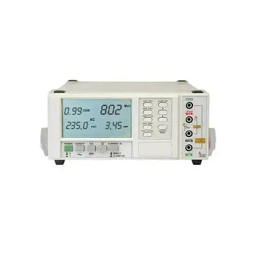
PXe-PA900 Series Power Analysers
PX Electronics PXe-PA900 Series Power Analysers provide accurate analytical AC measurement for loads (DUT) connected to SFC and AC power supplies. Designed for engineering laboratories, production test areas and field service environments, our range supports detailed measurement of voltage, current, power, harmonics, efficiency and energy performance across single-phase, three-phase and multi-channel systems.
Used alongside static frequency converters, programmable AC power sources, inverters, and electrical loads, the PA9xx Series helps engineers verify output performance, monitor load behaviour, and record reliable test data during commissioning, service checks, and product validation.
Technical Highlights for SFC Testing and Power Analysis:
Multi-channel power measurement
Configurable as a single or multi-channel analyser, with one to four measurement channels available depending on the selected arrangement.
Suitable for Static Frequency Converter testing
Supports SFC output checks including voltage, current, frequency, power, power factor, harmonic behaviour and load response during FAT, commissioning or diagnostics.
Modular channel card options
Available with a choice of channel card types, allowing the analyser to be specified around the test requirement rather than forcing a fixed configuration.
Input and output efficiency testing
Virtual Power Analysers can be configured for three phase measurement or input/output efficiency tests, helping engineers assess converter and power supply performance without using separate synchronised instruments.
Data logging for test evidence
Built-in data logging allows selected measurement results to be recorded to USB or internal storage, supporting commissioning records, customer test reports and repeatable validation procedures.
Harmonic and compliance options
Optional harmonic and compliance functions are available, including increased harmonic capability and EN61000 compliance computations where required.
Product Information
The PXe-PA900 Precision Multi-Channel Harmonic Power Analyser is designed for detailed measurement of AC power systems, including static frequency converters, programmable AC power sources, inverters, motor drives and connected electrical loads.
For PX static frequency converter projects, the PA900 can be used to verify converter output under realistic load conditions. It allows engineers to measure voltage, current, frequency, real power, apparent power, reactive power, power factor, harmonics and load response during factory acceptance testing, commissioning, service diagnostics and customer witness testing.
A single PA900 mainframe can be configured with up to four power measurement channels. This allows the analyser to be used for single-phase measurement, three-phase power analysis, converter output checks or input/output efficiency comparison. Virtual Power Analyser groupings allow channels to be arranged for multi-phase measurements or efficiency testing within a single instrument.
Channel card options allow the analyser to be matched to the test requirement. Standard channel cards are suitable for general power testing; high-accuracy cards offer tighter measurement uncertainty, and wideband cards support more demanding waveform analysis. Current input options include dual-shunt, higher-current, and external current-transducer configurations.
For SFC testing, the PA900 is useful when engineers need to confirm more than just basic front-panel readings. It can help identify waveform distortion, harmonic content, phase imbalance, power factor issues, inrush current and load-dependent behaviour that may not be obvious from voltage and frequency values alone.
The analyser includes diagnostic views for harmonic display, waveform capture, cycle view, vector display and historical trends. These tools help engineers investigate transient behaviour, changes in load conditions, and output quality during converter and power source testing.
Built-in data logging records selected measurement values for later review. This supports commissioning records, internal quality documentation, customer test reports and repeatable validation procedures.
Optional functions and accessories include extended harmonic capability, EN61000 compliance computations, rack mounting, carrying case and ISO 17025 calibration with data.
To specify a PXe-PA900 Power Analyser, the following information is normally required.
Measurement requirement
Confirm whether the analyser will be used for single phase testing, three phase testing, SFC output verification, converter input/output measurement, harmonic analysis, efficiency testing or general AC power measurement.
Number of measurement channels
Select the required number of channels. PA900 models are available with one to four power measurement channels.
Typical model arrangements include:
PXe-PA901-SD with 1 standard dual current channel card
PXe-PA902-SD with 2 standard dual current channel cards
PXe-PA903-SD with 3 standard dual current channel cards
PXe-PA904-SD with 4 standard dual current channel cards
PXe-PA901-AD with 1 high-accuracy dual shunt channel card
PXe-PA902-AD with 2 high-accuracy dual shunt channel cards
PXe-PA903-AD with 3 high-accuracy dual shunt channel cards
PXe-PA904-AD with 4 high-accuracy dual shunt channel cards
Accuracy and bandwidth requirement
Select the channel card type based on the required level of measurement performance. Standard, high-accuracy and wideband channel options are available depending on the application.
Current measurement method
Confirm the expected current range and preferred measurement method. Options include dual-shunt, higher-current, and external-current-transducer input configurations.
Harmonic and compliance requirements
Confirm whether an extended harmonic measurement is required. Optional H500 capability allows expanded harmonic analysis. EN61000 compliance computation options are also available where required.
Data and reporting requirements
Confirm whether the application requires data logging, screen capture, customer witness testing records, harmonic limits, commissioning evidence or ISO 17025 calibration data.
Available options and accessories:
-
- Extended harmonic measurement capability
- EN61000 compliance computation option
- Universal load power adaptor
- Hard carry/shipping case
- 19-inch rack mount kit
- ISO 17025 calibration with data
- External current transducer configurations
- Wideband channel card options
- High-current input options
For SFC projects, PX Electronics can advise on the most suitable PA900 configuration once the converter rating, output phase arrangement, current level, harmonic measurement requirement and required test evidence are known.
PXe-PA900 TECHNICAL SPECIFICATION
| Voltage Input Specifications | |||
| Channel Type | S or A Channel | W Channel | |
| Specified Input Range | DC | 0 to ±1000V | 0 to ±700V |
| AC | 0.1 to 1000Vrms | 0.1 to 700Vrms | |
| Peak | <1800V | <1800V | |
| Safe Input Range | <1ms | 2500Vrms (<3000Vpk) | 2000Vrms (<3000Vpk) |
| <100ms | 2000Vrms (<3000Vpk) | 1500Vrms (<3000Vpk) | |
| <5s | 1500Vrms (<2500Vpk) | 1000Vrms (<2500Vpk) | |
| Cont | 1000Vrms (<1800Vpk) | 700Vrms (<1800Vpk) | |
| Impedance | 1.2MΩ ± 1% | 400KΩ ± 1% | |
| Voltage Accuracy Specifications | |||
| The voltage input has a single dynamic range which covers the entire specified input range. | |||
| Channel Type | S Channel | A Channel | W Channel |
| Resolution | 0.001V | 0.1mV | 0.001V |
| Base Accuracy | 0.1% rdg | 0.03% rdg | 0.1% rdg |
| Frequency Adder | 0.01-1Hz: 0.05% rdg <10KHz: (0.005*F)% rdg 10-40KHz: (0.05+(0.012*(F-10)))% rdg 40-100KHz: (0.41+(0.025*(F-40)))% rdg |
0.01-1Hz: 0.1% rdg <40KHz: (0.002*F)% rdg 40-100KHz: (0.08+(0.004*(F-40)))% rdg 100-1000KHz: (0.32+(0.013*(F-100)))% rdg |
|
| Bandwidth (-3dB) | >700KHz | >2.5MHz | |
| Floor Adder | DC: 0.002V AC<100Hz: 0.003V AC>100Hz: 0.005V |
DC: 0.001V AC<100Hz: 0.002V AC>100Hz: 0.005V |
DC: 0.003V AC<100Hz: 0.004V AC>100Hz: 0.007V |
| Self-Heating Adder | >0.0005ppm rdg per Vrms2 | 0.0015ppm rdg per Vrms2 | |
| Single Harmonic Adder | <10KHz: 0.01%fund + 0.001V <85KHz: 0.05%fund + 0.005V |
<10KHz: 0.005%fund + 0.0005V <85KHz: 0.05%fund + 0.005V |
<10KHz: 0.015%fund + 0.0015V <100KHz: 0.03%fund + 0.005V <310KHz: 0.08%fund + 0.01V |
| ΣHarmonic Adder | <10KHz: 0.02%fund + 0.002V <85KHz: 0.1%fund + 0.01V |
<10KHz: 0.015%fund + 0.001V <85KHz: 0.15%fund + 0.01V |
<10KHz: 0.03%fund + 0.003V <100KHz: 0.06%fund + 0.007V <310KHz: 0.15%fund + 0.015V |
| CMRR | >1uV per V.Hz | 0.7uV per V.Hz | |
| Inter-Channel Phase | (0.02° + 0.15°*F) | (0.02° + 0.07°*F) | |
| Current Input Specifications | |||||||
| Option | H option | D option | X option | ||||
| AUTO range | HI range | LO range | HI range | LO range | |||
| Specified Input Range | DC | 0 to ±30A | 0 to ±20A | 0 to ±20A | 0 to ±1A | 0 to ±15V | 0 to ±0.5V |
| <100Hz | 3mA to 30Arms | 10uA to 20Arms | 2mA to 20Arms | 10uA to 1Arms | 800uV to 15Vrms | 20uV to 0.5Vrms | |
| >100Hz | 20mA to 30Arms | 150uA to 20Arms | 15mA to 20Arms | 150uA to 1Arms | 2mV to 15Vrms | 80uV to 0.5Vrms | |
| Peak | <200A | <50A | <150A | <1A | <18V | <0.5V | |
| Safe Input Range | <1ms | 200Arms (<300Apk) | 30Arms (<50Apk) | 150Arms (<250Apk) | 30Arms (<50Apk) | 200Arms (300Apk) | 20Arms (300Apk) |
| <20ms | 75Arms (<300Apk) | 20Arms (<50Apk) | 50Arms (<200Apk) | 20Arms (<50Apk) | 50Vrms (300Vpk) | 10Vrms (200Vpk) | |
| <1s | 50Arms (<200Apk) | 20Arms (<50Apk) | 30Arms (<150Apk) | 5Arms (<25Apk) | 30Vrms (300Vpk) | 5Vrms (100Vpk) | |
| Cont | 30Arms | 20Arms (<50Apk) | 20Arms (<150Apk) | 2Arms (<5Apk) | 20Vrms (300Vpk) | 2Vrms (50Vpk) | |
| Power Off | As Above | As LO Range | As Above | As HI Range | |||
| Impedance | <10mΩ | As HI/LO range | <20mΩ | 0.57Ω ± 10% | 20.5KΩ ± 1% | 10.25KΩ ± 1% | |
| H Option Current Measurement Accuracy Specifications | |||
| The H option current input has a single range which covers the entire specified input range. | |||
| Channel Type | S Channel | A Channel | W Channel |
| Resolution | 100uA | 10uA | 100uA |
| Base Accuracy | 0.1%rdg | 0.03%rdg | 0.1%rdg |
| Frequency Adder | 0.01‐1Hz: 0.05% rdg <10KHz: (0.003*F)% rdg 10‐40KHz: (0.03+(0.007*(F‐10)))% rdg 40-100KHz: (0.24+(0.02*(F‐40)))% rdg |
0.01‐1Hz: 0.1% rdg <40KHz: (0.0015*F)% rdg 40‐100KHz: (0.06+(0.003*(F-40)))% rdg 100‐1000KHz: (0.24+(0.012*(F‐100)))% rdg |
|
| Bandwidth (-3dB) | >1.25MHz | >5MHz | |
| Floor Adder | DC: 200uA AC<100Hz: 800uA AC>100Hz: 3mA |
DC: 100uA AC<100Hz: 500uA AC>100Hz: 2mA |
DC: 300uA AC<100Hz: 1mA AC>100Hz: 4mA |
| Self-Heating Adder | 1.5ppm reading per Arms2 | ||
| Single Harmonic Adder | <10KHz: 0.01%fund + 100uA <85KHz: 0.05%fund + 5mA |
<10KHz: 0.005%fund + 80uA <85KHz: 0.03%fund + 5mA |
<10KHz: 0.015%fund + 150uA <100KHz: 0.03%fund + 5mA <310KHz: 0.08%fund + 5mA |
| ΣHarmonic Adder | <10KHz: 0.02%fund + 200uA <85KHz: 0.1%fund + 7mA |
<10KHz: 0.015%fund + 150uA <85KHz: 0.15%fund + 7mA |
<10KHz: 0.03%fund + 300uA <100KHz: 0.06%fund + 7mA <310KHz: 0.15%fund + 10mA |
| CMRR | 500pA per V.Hz | ||
| V:A Phase | (0.01° + 0.015°*F) | (0.01° + 0.007°*F) | |
| Inter-Channel Phase | (0.02° + 0.15°*F) | (0.02° + 0.07°*F) | |
| D Option HI Range Current Measurement Accuracy Specifications | |||
| The D option current input has two ranges; this section covers the HI range, which covers the entire specified HI input range. | |||
| Channel Type | S Channel | A Channel | W Channel |
| Resolution | 100uA | 10uA | 100uA |
| Base Accuracy | 0.1%rdg | 0.03%rdg | 0.1%rdg |
| Frequency Adder | 0.01‐1Hz: 0.05%rdg <10KHz: (0.003*F)%rdg 10‐40KHz: (0.03+(0.007*(F-10)))%rdg 40-100KHz: (0.24+(0.02*(F‐40)))%rdg |
0.01‐1Hz: 0.1%rdg <40KHz: (0.0015*F)%rdg 40‐100KHz: (0.06+(0.003*(F‐40)))%rdg 100‐1000KHz: (0.24+(0.012*(F‐100)))%rdg |
|
| Bandwidth (-3dB) | >1.25MHz | >5MHz | |
| Floor Adder | DC: 200uA AC<100Hz: 500uA AC>100Hz: 2mA |
DC: 100uA AC<100Hz: 300uA AC>100Hz: 1.5mA |
DC: 300uA AC<100Hz: 700uA AC>100Hz: 3mA |
| Self-Heating Adder | 2ppm reading per Arms2 | ||
| Single Harmonic Adder | <10KHz: 0.01%fund + 70uA <85KHz: 0.05%fund + 3.5mA |
<10KHz: 0.005%fund + 50uA <85KHz: 0.03%fund + 3.5mA |
<10KHz: 0.015%fund + 100uA <100KHz: 0.03%fund + 3.5mA <310KHz: 0.08%fund + 4mA |
| ΣHarmonic Adder | <10KHz: 0.02%fund + 150uA <85KHz: 0.1%fund + 5mA |
<10KHz: 0.015%fund + 120uA <85KHz: 0.15%fund + 5mA |
<10KHz: 0.03%fund + 200uA <100KHz: 0.06%fund + 5mA <310KHz: 0.15%fund + 7mA |
| CMRR | 400pA per V.Hz | ||
| V:A Phase | (0.01° + 0.015°*F) | (0.01° + 0.007°*F) | |
| Inter-Channel Phase | (0.02° + 0.15°*F) | (0.02° + 0.07°*F) | |
| D Option LO Range Current Measurement Accuracy Specifications | |||
| The D option current input has two ranges; this section covers the LO range, which covers the entire specified LO input range. | |||
| Channel Type | S Channel | A Channel | W Channel |
| Resolution | 1uA | 0.1uA | 1uA |
| Base Accuracy | 0.1% rdg | 0.03% rdg | 0.1% rdg |
| Frequency Adder | 0.01‐1Hz: 0.05% rdg <10KHz: (0.003*F)% rdg 10‐40KHz: (0.03+(0.007*(F-10)))% rdg 40-100KHz: (0.24+(0.02*(F‐40)))% rdg |
0.01‐1Hz: 0.1% rdg <40KHz: (0.0015*F)% rdg 40‐100KHz: (0.06+(0.003*(F‐40)))% rdg 100‐1000KHz: (0.24+(0.012*(F-100)))% rdg |
|
| Bandwidth (-3dB) | >1.25MHz | >6MHz | |
| Floor Adder | DC: 2uA AC<100Hz: 3uA AC>100Hz: 10uA |
DC: 1uA AC<100Hz: 1.5uA AC>100Hz: 8uA |
DC: 3uA AC<100Hz: 4uA AC>100Hz: 15uA |
| Single Harmonic Adder | <10KHz: 0.01%fund + 0.4uA <85KHz: 0.05%fund + 20uA |
<10KHz: 0.005%fund + 0.3uA <85KHz: 0.03%fund + 20uA |
<10KHz: 0.015%fund + 0.5uA <100KHz: 0.03%fund + 20uA <310KHz: 0.08%fund + 30uA |
| ΣHarmonic Adder | <10KHz: 0.02%fund + 1uA <85KHz: 0.1%fund + 30uA |
<10KHz: 0.015%fund + 0.7uA <85KHz: 0.15%fund + 30uA |
<10KHz: 0.03%fund + 1uA <100KHz: 0.06%fund + 30uA <310KHz: 0.15%fund + 40uA |
| CMRR | 20pA per V.Hz | ||
| V:A Phase | (0.01° + 0.015°*F) | (0.01° + 0.007°*F) | |
| Inter-Channel Phase | (0.02° + 0.15°*F) | (0.02° + 0.07°*F) | |
| X Option HI Range Current Measurement Accuracy Specifications | |||
| The X option current input has two ranges; this section covers the HI range, which covers the entire specified HI input range. | |||
| Channel Type | S Channel | A Channel | W Channel |
| Resolution | 1uV | 0.1uV | 1uV |
| Base Accuracy | 0.1% rdg | 0.03% rdg | 0.1% rdg |
| Frequency Adder | 0.01-1Hz: 0.05% rdg <10KHz: (0.003*F)% rdg 10‐40KHz: (0.03+(0.007*(F‐10)))% rdg 40-100KHz: (0.24+(0.02*(F‐40)))% rdg |
0.01‐1Hz: 0.1% rdg <40KHz: (0.0015*F)% rdg 40‐100KHz: (0.068+(0.004*(F-40)))% rdg 100‐1000KHz: (0.308+(0.015*(F‐100)))% rdg |
|
| Bandwidth (-3dB) | >1.25MHz | >3MHz | |
| Floor Adder | DC: 2uV AC<100Hz: 2uV AC>100Hz: 8uV |
DC: 1uV AC<100Hz: 1.5uV AC>100Hz: 5uV |
DC: 2uV AC<100Hz: 3uV AC>100Hz: 10uV |
| Single Harmonic Adder | <10KHz: 0.01%fund + 0.3uV <85KHz: 0.05%fund + 10uV |
<10KHz: 0.005%fund + 0.1uV <85KHz: 0.03%fund + 10uV |
<10KHz: 0.015%fund + 0.3uV <100KHz: 0.03%fund + 10uV <310KHz: 0.08%fund + 15uV |
| ΣHarmonic Adder | <10KHz: 0.02%fund + 0.5uV <85KHz: 0.1%fund + 15uV |
<10KHz: 0.015%fund + 0.3uV <85KHz: 0.15%fund + 15uV |
<10KHz: 0.03%fund + 0.5uV <100KHz: 0.06%fund + 15uV <310KHz: 0.15%fund + 20uV |
| CMRR | 1nV per V.Hz | ||
| V:A Phase | (0.01° + 0.015°*F) | (0.01° + 0.007°*F) | |
| Inter-Channel Phase | (0.02° + 0.15°*F) | (0.02° + 0.07°*F) | |
| X Option LO Range Current Measurement Accuracy Specifications | |||
| The X option current input has two ranges; this section covers the LO range, which covers the entire specified LO input range. | |||
| Channel Type | S Channel | A Channel | W Channel |
| Resolution | 1uV | 0.1uV | 1uV |
| Base Accuracy | 0.1% rdg | 0.03% rdg | 0.1% rdg |
| Frequency Adder | 0.01‐1Hz: 0.05% rdg <10KHz: (0.003*F)% rdg 10‐40KHz: (0.03+(0.007*(F‐10)))% rdg 40-100KHz: (0.24+(0.02*(F‐40)))% rdg |
0.01‐1Hz: 0.1% rdg <40KHz: (0.0015*F)% rdg 40‐100KHz: (0.068+(0.004*(F‐40)))% rdg 100‐1000KHz: (0.308+(0.015*(F‐100)))% rdg |
|
| Bandwidth (-3dB) | >1.25MHz | >3MHz | |
| Floor Adder | DC: 2uV AC<100Hz: 2uV AC>100Hz: 8uV |
DC: 1uV AC<100Hz: 1.5uV AC>100Hz: 5uV |
DC: 2uV AC<100Hz: 3uV AC>100Hz: 10uV |
| Single Harmonic Adder | <10KHz: 0.01%fund + 0.3uV <85KHz: 0.05%fund + 10uV |
<10KHz: 0.005%fund + 0.1uV <85KHz: 0.03%fund + 10uV |
<10KHz: 0.015%fund + 0.3uV <100KHz: 0.03%fund + 10uV <310KHz: 0.08%fund + 15uV |
| ΣHarmonic Adder | <10KHz: 0.02%fund + 0.5uV <85KHz: 0.1%fund + 15uV |
<10KHz: 0.015%fund + 0.3uV <85KHz: 0.15%fund + 15uV |
<10KHz: 0.03%fund + 0.5uV <100KHz: 0.06%fund + 15uV <310KHz: 0.15%fund + 20uV |
| CMRR | 1nV per V.Hz | ||
| V:A Phase | (0.01° + 0.015°*F) | (0.01° + 0.007°*F) | |
| Inter-Channel Phase | (0.02° + 0.15°*F) | (0.02° + 0.07°*F) | |
| Watts, VAR and VA Measurement Accuracy Specifications | |||
| Fundamental Phase Adder (for W or VAR only, typically can be ignored for active loading, where the PF is reduced by distortion rather than phase shift. K is 0.3 for Watts, harmonic VAR and harmonic VA; otherwise, 1.0. | |||
| Channel Type | S Channel | A Channel | W Channel |
| Base Accuracy | 0.17% rdg | 0.05% rdg | 0.17% rdg |
| Frequency Adder | Add Frequency Adders for voltage and current | ||
| Floor Adder | DC: Vdc*(DC Current Floor Adder) + Adc*(DC Voltage Floor Adder) + (DC Voltage Floor Adder)*(DC Current Floor Adder) AC: Vac*K*(AC Current Floor Adder) + Aac*K*(AC Voltage Floor Adder) |
||
| Fundamental Phase Adder | Watts: VAfund*(PFfund – cos(cos-1(PFfund) + V:A phase for current input)) VAR: VAfund*((1-PFfund) – cos(cos-1(1-PFfund) + V:A phase for current input)) |
||
| Self-Heating Adder | Add Self-Heating Adders for voltage and current | ||
| Single Harmonic Adder | Add Single Harmonic Adders for voltage and current | ||
| ΣHarmonic Adder | Add ΣHarmonic Adders for voltage and current | ||
No matching FAQs found.
The PXe-PA900 measures key AC power parameters, including voltage, current, watts, VA, VAR, power factor, frequency, harmonics, and energy. It can also be configured for waveform, vector, and cycle displays, as well as historical trend views, providing engineers with more information than a basic power meter.
Yes. The PXe-PA900 can be used to test static frequency converters by measuring output voltage, current, frequency, real power, apparent power, reactive power, power factor, harmonics and load response. However, the main use for a power analyser is measuring from the SFC to the load under test. This is useful during factory acceptance testing, commissioning, fault investigation and customer witness testing.
PX should confirm the SFC output phase arrangement with the customer, voltage, expected current, load type, whether input/output efficiency is required, whether harmonic analysis is required, the preferred current measurement method and whether recorded data or ISO 17025 calibration is needed. For 400Hz systems, the required harmonic range, intended current sensor bandwidth and any aviation test requirements should also be confirmed.
Typically 3, but that depends on the input/output arrangement and the test objectives. A single phase output may only require one channel. A three phase system typically requires multiple channels, especially when assessing total power, phase imbalance, phase-to-phase behaviour, or input/output efficiency. The PA900 can be configured with up to four power measurement channels (channel combinations can be described as Virtual Power Analyser VPA).
The current input option depends on the expected current level and measurement method. Direct shunt inputs are useful for precision measurement; higher-current inputs suit heavier loads; and the “X” option, a voltage input for external current transducer inputs, is useful when clamps, CTs, or other external sensors are preferred. PX Electronics would confirm the current range and optimal test setup before specifying the analyser.
Yes. The PXe-PA900 supports voltage and current harmonic analysis with absolute measurement or bargraph displays. This is useful for 400Hz Static Frequency Converter testing, avionics power checks, and applications where waveform quality needs to be reviewed or documented for conformance.
Yes, with the correct channel configuration. Engineers can use multiple channels to compare converter input and output power, which is useful for checking efficiency, losses, cooling and load-dependent performance in static frequency converters, programmable AC sources, and inverter systems. Typically CH1, CH2 (2 wattmeter method) for converter input and CH3, CH4 for the converter output.
Yes. The PXe-PA900 includes measurement and display functions that can help engineers investigate inrush and transient behaviour. This is useful when testing transformers, motors, rectifier inputs, capacitive input power supplies and other loads connected to a static frequency converter.
The front panel wattmeter display on a static frequency converter is useful for operational checks, but it does not provide the same level of measurement detail as a dedicated power analyser. The PXe-PA900 allows engineers to examine waveform quality, harmonic content, inrush current, phase imbalance, power factor, and load-dependent behaviour more closely.
Yes. The PXe-PA900 can record selected measurement values for later review. This supports FAT documentation, commissioning packs, customer witness testing, service reports and internal quality records. The power analyser is supplied with calibration certificates.
Yes. ISO 17025-accredited calibration with data is available as a chargeable option and is performed by an external Laboratory. This should be specified when traceable measurement evidence is required for customer acceptance, audit records, or formal validation work.
A power meter is generally used for straightforward measurements such as watts, voltage, current, and energy consumption. A power analyser provides deeper measurement and diagnostic capability, including harmonic analysis, phase relationships, waveform capture, power factor behaviour and multi-channel efficiency testing.
A power analyser is a test instrument used to measure electrical power behaviour in more detail than a standard wattmeter. Power analysers can typically measure complex waveshapes and can measure voltage, current, crest factors, real power, apparent power, reactive power, power factor, frequency, harmonics and energy consumption, depending on the model and configuration.