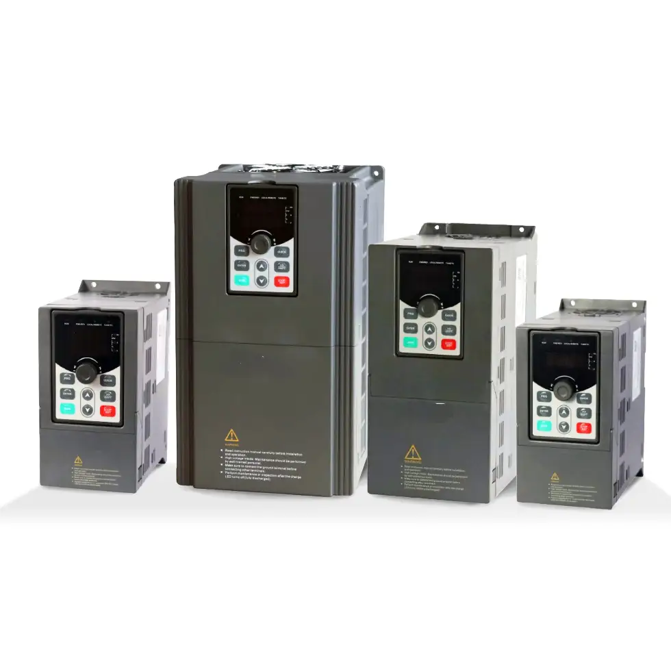
PXe-PI150 Variable Speed Motor Drive
PX Electronics PI150 variable speed motor drives provide compact, reliable control for AC motors used in fans, pumps, conveyors, compressors and light industrial machinery. With V/F control, sensorless vector control, built-in PID, and RS485 communication, the PI150 Series is suited for control panels, automation systems, and variable-load applications that require stable motor speed regulation.
Technical Highlights for Motor Control Applications:
Compact variable speed drive
Designed for space-conscious control panels and machinery installations that require reliable motor speed control.
Vector and V/F control modes
Supports V/F control and sensorless vector control for a wide range of standard motor applications.
Suitable for fans, pumps and conveyors
Provides controlled acceleration, deceleration and speed regulation for common industrial and commercial loads.
Built-in PID control
Useful for pressure, flow and process control applications, including pump, fan and ventilation systems.
Multiple control inputs
Supports panel operation, terminal control and serial communication for integration into wider control systems.
RS485 communication as standard
Built-in RS485 allows the drive to be connected to automated systems that require remote control or monitoring.
Integrated protection functions
Includes protection against overvoltage, undervoltage, overcurrent, overload, overheating and short circuit conditions.
The PXe-PI150 Variable Speed Motor Drive is ideally suited for a wide range of industrial and commercial applications where precise motor control and energy efficiency are essential. Its compact footprint, intelligent control features, and low power consumption make it an excellent choice for:
HVAC Systems
For optimising fan and pump performance while reducing energy costs
Conveyor Systems
Ensuring smooth acceleration and deceleration for material handling.
Packaging Machinery
Providing accurate torque and speed control for consistent output.
Pumps and Compressors
Improving operational efficiency and reducing mechanical stress.
Automation Equipment
Enabling fine-tuned control in robotics, CNC machines, and assembly lines.
Agricultural And Irrigation Systems
Offering reliable motor control in demanding outdoor environments.
Applications

Operating environment:
Environment temperature
-10 ℃ to 50 ℃, temperature at 40 ℃ or above derate at 3% per 1°C drop. It is not recommended to use the inverter above 50°C
Electromagnetic interference
Measures taken to prevent electromagnetic interference, EN IEC61000-3-2, EN 61000-3-3, EN55032, EN55035, MIL-STD-1399, MIL-STD 461, MIL-STD704, STANAG 1008
Intrusion of particulates
User should observe procedures to prevent intrusion of water droplets, steam, dust, fluff and metal filings
Chemical Intrusion
Do not use in spaces where corrosive gases are present, observe contamination controls of oil, salt and corrosive gases
Vibrations
Max vibration cannot cannot exceed 5.9m/s (0.6g).
Temperature and Humidity
Avoidance of high temperature, humidity and ingress of water. Do not allow condensation, relative humidity is less than 90%, the maximum relative humidity cannot exceed 60%.
Flammables
Not to be used in vicinity of explosive gas, liquid or solid hazardous chemicals.
Altitude
There is no degradation under 1000m, degrade 1% for altitude rise of 100m when above 1000m, not suitable for use over 3000m
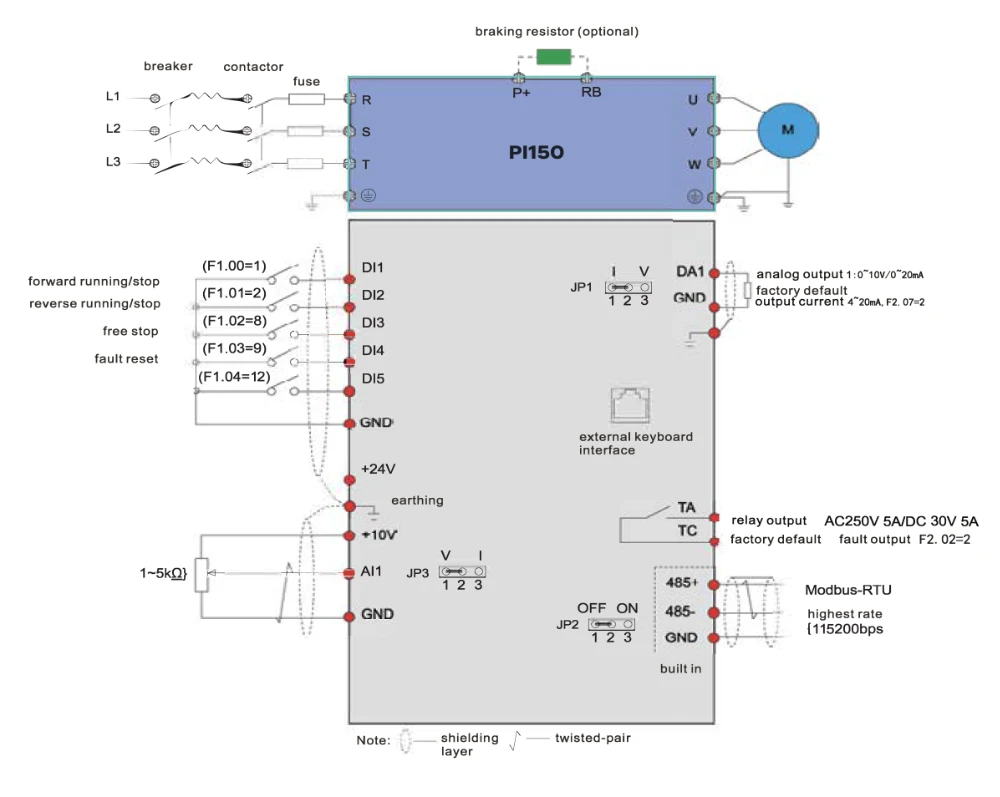
Wiring Diagram
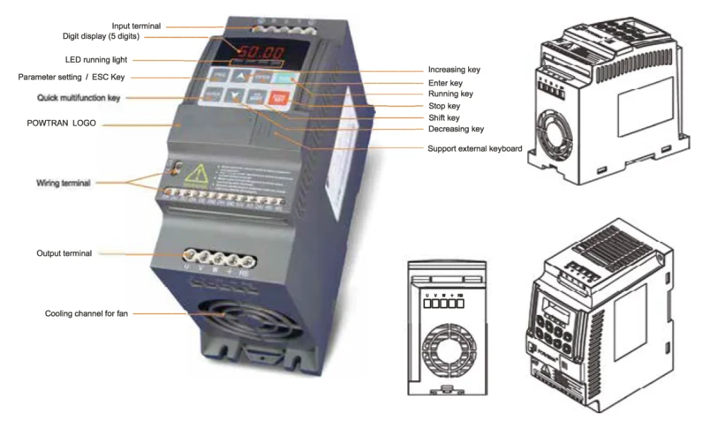
Configuration
Technical Specification
| Power | |||
| Rated Voltage | AC 3PH 380V (-15%) ~440V (+10%) | ||
| Input Frequency | 50Hz/60Hz | ||
| Allowing Fluctuations | Voltage continued volatility: ±10% | Less than 3% of voltage unbalance rate 3% | |
| Allowing Fluctuations | Input frequency fluctuation: ±5% | Distortion satisfy IEC61800-2 standard | |
| Control | |||
| Control System | High performance vector control inverter based on DSP | ||
| Control Method | V/F control, vector control W/O PG | ||
| Automatic Torque Boost Function | Realise low frequency (1Hz) and large output torque control under the V/F control mode | ||
| Acceleration/Deceleration Control | Straight or S-curve mode. Four times available and time range is 0.0 to 6500.0s | ||
| V/F Curve Mode | Linear, square root/m-th power, custom V/F curve | ||
| Over Load Capability | G type:rated current 150% – 1 minute, rated current 180% – 2 seconds | ||
| Maximum Frequency | 1、Vector control:0 to 300Hz; 2、V/F control:0 to 3200Hz | ||
| Carrier Frequency | 0.5 to 16kHz; automatically adjust carrier frequency according to the load characteristics | ||
| Input Frequency Resolution | Digital setting: 0.01Hz Analog setting: maximum frequency*0.025% |
||
| Start Torque | G type: 0.5Hz/150% (vector control W/O PG) | ||
| Speed Range | 1:100 (vector control W/O PG) | ||
| Steady-Speed Precision | Vector control W/O PG: ≤ ± 0.5% (rated synchronous speed) | ||
| Torque Response | ≤ 40ms (vector control W/O PG) | ||
| Torque Boost | Automatic torque boost; manual torque boost (0.1% to 30.0%) | ||
| DC Braking | DC braking frequency: 0.0Hz to max. frequency braking time: 0.0 to 100.0 seconds braking current value: 0.0% to 100.0% |
||
| Jogging Control | Jog Frequency Range: 0.00Hz to max. frequency Jog Ac/deceleration time: 0.0s to 6500.0s |
||
| Built-in PID | Easy to realise closed-loop control system for process control | ||
| Automatic Voltage Regulation (AVR) | Automatically maintain a constant output voltage when the voltage of electricity grid changes | ||
| Torque Limit and Control | Automatically track current motor torque when the inverter starts | ||
| Personalisation Function | |||
| Self-inspection of Peripherals after Power-on | After powering on, peripheral equipment will perform safety testing, such as ground, short circuit etc. | ||
| Quick Current Limiting | The current limiting algorithm is used to reduce the inverter over current probability, and improve whole unit anti-interference capability | ||
| Timing Control | Timing control function: time setting range (0m to 6500m) | ||
| Running | |||
| Input Signal | DI Input Terminal | 5 digital input terminals | |
| Input Signal | AI1 Analog Input | 1 analog input terminals respectively for optional range (0 to 20mA or 0 to 10V) | |
| Input Signal | Multi-Speed | At most 16-speed can be set (run by using the multi-function terminals or program) | |
| Input Signal | Emergency Stop | Interrupt controller output | |
| Input Signal | Fault Reset | When the protection function is active, you can automatically or manually reset the fault condition | |
| Input Signal | PID Feedback Signal | Including DC (0 to 10V), DC (0 to 20mA) | |
| Output Signal | Output Signal | One way relay output; One way AD1 analog output | |
| Output Signal | Relay Output | There are 40 signals each way. Contact capacity: normally open contact 5A/AC 250V, 1A/DC 30V |
|
| Output Signal | DA1 Analog Output | One way analog output, can select frequency, current, voltage etc 16 signals. Output signals can be sent 0~10V/0~20mA | |
| Running Command Channel | Three channels: operation panel, control terminals and serial communication port. They can be switched through a variety of ways | ||
| Frequency Source | Total 7 frequency sources: digital, analog voltage, analog current, multi-speed and serial port. They can be switched through a variety of ways | ||
| Run Function | Limit frequency, jump frequency, frequency compensation, auto-tuning, PID control | ||
| Protection Function | |||
| Inverter Protection | Overvoltage protection, undervoltage protection, overcurrent protection, overload protection, overheat protection, overcurrent stall protection, overvoltage stall protection, lost-phase protection (optional), communication error, PID feedback signal abnormalities, PG failure and short circuit to ground protection | ||
| Display | |||
| LED Display Keyboard | Running Information | Monitoring objects including: running frequency, set frequency, bus voltage, output voltage, output current, output power, output torque, input terminal status, output terminal status, analog AI1 value, motor Actual running speed, PID set value percentage, PID feedback value percentage | |
| LED Display Keyboard | Error Message | Up to three error messages are saved. The time, type, voltage, current, frequency and work status can be queried when a failure has occurred | |
| Key Lock and Function Selection | The keypad can be partially or fully locked, define the function scope of some keys to prevent misuse | ||
| IGBT Temperature | Show the inverter inner IGBT temperature | ||
| Communication | |||
| RS485 | Built in 485 | ||
| Environment | |||
| Environment Temperature | -10℃ to 40℃ (temperature at 40℃to 50℃, please derating for use) | ||
| Storage Temperature | -20℃ to 65℃ | ||
| Environment Humidity | Less than 90% R.H, no condensation | ||
| Vibration | Below 5.9m/s²(= 0.6g) | ||
| Application Sites | Indoor where no sunlight, corrosive substance, explosive gas, water vapour, dust, flammable gas, oil, mist, salt, etc | ||
| Altitude | No need to degrade use under 1000m, degrade 1% for altitude rise 100m when above 1000m, do not use it above 3000m | ||
| Protection Level | IP20 | ||
| Product Standard | |||
| Product Adopts Safety Standards | IEC61800-5-1:2007 | ||
| Product Adopts EMC Standards | IEC61800-3:2005 | ||
| Cooling Method | Forced air cooling | ||
| Install Method | DIN-Rail mounting, wall mounting | ||