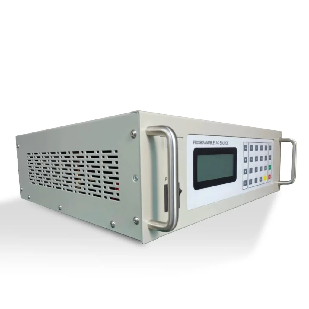
PXe-BLS Dual Redundant AC Power Supplies
PX Electronics BLS dual redundant AC power supplies provide continuous AC output for critical systems using automatic selection between DC input and AC bypass supply. Designed for telecoms, SCADA, utilities, transport networks, and control room environments, the system helps maintain power to essential AC loads, minimising interruptions.
With pure sine-wave output, rack-mount construction, fast bypass transfer, remote-monitoring interfaces, and dry-contact alarms, the PXe-BLS Series is suited for unattended infrastructure, communication sites, and industrial control systems that require dependable backup AC power.
Technical Highlights for Critical AC Power Applications:
Dual input supply architecture
Automatically selects between DC input and AC bypass supply to maintain AC output to connected critical loads.
Pure sine wave output
Provides clean AC output with low harmonic distortion, suitable for sensitive communication, control and monitoring equipment.
Fast automatic transfer
Switches between supply modes in up to 5 ms, helping reduce disruption during AC input failure or DC supply fault conditions.
Rack-mount installation
Standard 19-inch rack-mount enclosure for telecoms rooms, control cabinets, substations and data infrastructure sites.
Remote monitoring and alarms
Supports RS232, RS485, Modbus RTU and TCP/IP communication options, with volt-free contacts for input fault and system status indication.
Built-in protection functions
Includes overload, short circuit, over-temperature, DC input voltage and AC input voltage protection for critical power applications.
Maintenance bypass
Allows service access and system maintenance while supporting continuity of supply to the connected load.
Dual input operation
Automatically selects between DC input and AC bypass input to maintain AC output to the connected critical load.
Fast automatic transfer
Switches between DC inverter operation and AC bypass in up to 5 ms.
True sine wave output
Provides a true sine-wave AC output with low harmonic distortion for sensitive electrical equipment.
Built-in voltage regulation
Stabilises AC output voltage to support the reliable operation of connected systems.
Monitoring and alarms
Provides system status, fault reporting, bypass status, audible alarms and visual indication.
Remote communication options
Supports RS232, RS485, Modbus RTU and TCP/IP communication ports.
Volt-free fault contacts
Includes volt-free contacts for DC input fault and AC input fault indication.
Start-up and operating control
Includes power-on self-test, soft-start output, and automatic temperature-controlled fan operation.
Maintenance bypass
Allows service access while maintaining the connected load’s continuity of supply.
Built-in protection
Includes short-circuit protection, overload protection, and battery overvoltage/undervoltage protection.
Rack-mount construction
Supplied in a standard 19-inch rack-mount enclosure for infrastructure and control system installations.
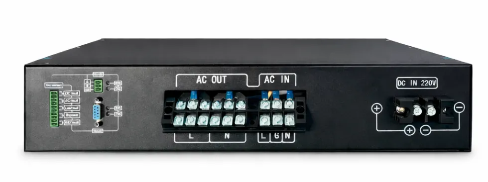
PX-BLS Back Panel
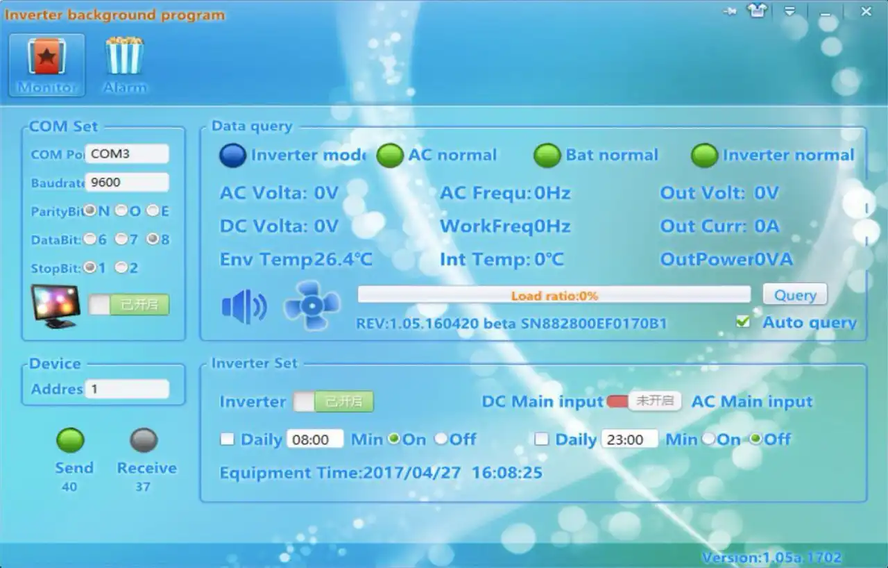
Comms Background Program
Hardware structure and working principle
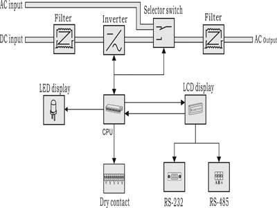
AC power supply mode
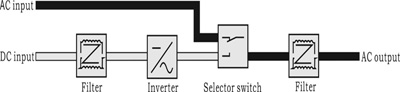
Namely AC inverter working mode: the inverter employs mains for load when there is mains and switches to inverter working mode when the mains is abnormal.
DC power supply mode
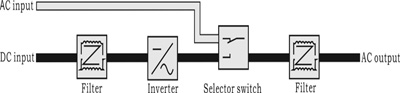
Namely DC-dominated inverter working mode: under normal condition, DC-dominated inverter is under inverter output status all the time; in case of DC fault, it switches to mains by-pass.
Technical Specification
| Technical Index (VA) | 1KVA | 2KVA | 3KVA | 4KVA | 5KVA | 6KVA | 8KVA | 10KVA | ||
| Input | ||||||||||
| 22Vdc—28Vdc | Rate Voltage 24Vdc, Power off Voltage: ≤20Vdc, ≥30Vdc | |||||||||
| 45.5Vdc—57Vdc | Rate Voltage 48Vdc, Power off Voltage: ≤40Vdc, ≥60Vdc | |||||||||
| 104Vdc—131Vdc | Rate Voltage 110Vdc, Power off Voltage: ≤90Vdc, ≥135Vdc | |||||||||
| 208Vdc—260Vdc | Rate Voltage 220Vdc, Power off Voltage: ≤180Vdc, ≥275Vdc | |||||||||
| 24Vdc Input Max Current | 42A/42A | 83A/83A | 125A/125A | X | X | X | X | X | ||
| 48Vdc Input Max Current | 21A/21A | 42A/42A | 63A/63A | 83A/83A | 104A/104A | 125A/125A | 167A/X | 208A/X | ||
| 110Vdc Input Max Current | 9A/9A | 18A/18A | 27A/27A | 36A/36A | 45A/45A | 55A/55A | 72A/X | 90A/X | ||
| 220Vdc Input Max Current | 4.5A/4.5A | 9A/9A | 13.5A/13.5A | 18A/18A | 22.5A/22.5A | 27A/27A | 36A/X | 45A/X | ||
| By-pass | Voltage Range | 180Vac~260VAC/90Vac~132Vac | ||||||||
| By-pass | Current | 4.5A/8.3A | 9.1A/16.5A | 13.6A/26A | 18.2A/33A | 22.7A/41A | 27.2A/50A | 36.3A/X | 45.4A/X | |
| By-pass | By-pass Transient Time | ≤5ms | ||||||||
| Frequency | 50/60Hz | |||||||||
| AC Output | ||||||||||
| Output Capacity(VA) | 1KVA | 2KVA | 3KVA | 4KVA | 5KVA | 6KVA | 8KVA | 10KVA | ||
| Rated Output Power(W) | 0.8KW | 1.6KW | 2.4KW | 3.2KW | 4KW | 4.8KW | 6.4KW | 8KW | ||
| Rated Output Current | 3.6A | 7.3A | 11A | 14.5A | 18.2A | 21.8A | 29A | 36.3A | ||
| Output Voltage | 220Vac(±10V)/110V(±5V), Adjustable LCD display | |||||||||
| Output Voltage Precision(V) | 220V±1.5%/110V±1.5% | |||||||||
| Power Factor | >0.8 | |||||||||
| Inversion Efficiency(80%) | ≥85%(80% liner Load) | |||||||||
| Over Load | 100%-120% 60s, 121%-150% 10s | |||||||||
| Dynamic Response Time | Dynamic Response Time: < 5% Vnom for load change 0% to 100%, transient time < 5ms | |||||||||
| Waveform | Pure Sine Wave | |||||||||
| By-pass Switch Time | ≤5ms | |||||||||
| Output Frequency Precision | 50Hz/60Hz | |||||||||
| Output Frequency | 50-60Hz (auto sync with bypass input) | |||||||||
| THD | ≤3% | |||||||||
| Indication | ||||||||||
| LCD Display | Input and Output Voltage, Frequency, Output Current, Temperature, Percentage, LOGO etc. | |||||||||
| Inverter Status | Normal Mains, Normal Inversion, Battery, Under-Voltage and Output Overload | |||||||||
| Compliance | ||||||||||
| LVD | EN 60950-1 | |||||||||
| EMC/EMI | EN 61000-6-3; EN 61000-6-1; IEC 61000-6-2 and IEC 61000-6-4 | |||||||||
| Cooling | ||||||||||
| Temperature Control | 2 Fans | 4 Fans | 6 Fans | 4 Fans | ||||||
| Colour | ||||||||||
| Colour | Black/Customisable | |||||||||
| Dimensions | ||||||||||
| Dimensions | 482mm/347mm/88mm W/D/H 2U | 482mm/430mm/88mm W/D/H 2U | 482mm/470mm/176mm 4U | |||||||
| Protection | ||||||||||
| Internal Protection | Overload Protection, Over temperature protection, Short circuit protection, Input AC voltage limit protection, Reverse polarity on DC input side | |||||||||
| Input DC Voltage Alarm | Battery Under-Voltage | |||||||||
| LCD Audible and Visual Alarm | False Red LED light and Beep | |||||||||
| Temperature | Temperature Control Fan | |||||||||
| Alarm Record | Standard is 1000 events (alarms), minimum is 100 | |||||||||
| Interface | ||||||||||
| 5 Routes Dry Relay Contact | For remote indication of alarm/shut down conditions | |||||||||
| RS232& RS485 | Both available, for remote operation and monitoring | |||||||||
| Option | SNMP, TCP/IP | |||||||||
| Dielectric Strength | ||||||||||
| Between Output and Input | 3500Vdc/10mA/1min. No flashover, no breakdown | |||||||||
| Between input and chassis | 3500Vdc/10mA/1min. No flashover, no breakdown | |||||||||
| Between Output and Chassis | 750Vdc/10mA/1min. No flashover, no breakdown | |||||||||
| Dielectric Strength | 1500Vac. 1 minute (Input and output) | |||||||||
| Working Environment | ||||||||||
| Noise (1m) | ≤40dB | |||||||||
| Operating Environment Temperature | -20℃~+50℃ | |||||||||
| Humidity | 0~90%, No moisture condensation | |||||||||
| Operating Altitude (m) | Altitude Full power up to 2000m. Derating -2% / 100m, max altitude 5000m | |||||||||
| Humidity | 5…95%, non condensing | |||||||||