| Power |
| Rated Voltage |
AC 3PH 380V (-15%) ~440V (+10%) |
| Input Frequency |
50Hz/60Hz |
| Allowing Fluctuations |
Voltage continued volatility: ±10% |
Less than 3% of voltage unbalance rate 3% |
| Allowing Fluctuations |
Input frequency fluctuation: ±5% |
Distortion satisfy IEC61800-2 standard |
| Control |
| Control System |
High performance vector control inverter based on DSP |
| Control Method |
V/F control, vector control W/O PG |
| Automatic Torque Boost Function |
Realise low frequency (1Hz) and large output torque control under the V/F control mode |
| Acceleration/Deceleration Control |
Straight or S-curve mode. Four times available and time range is 0.0 to 6500.0s |
| V/F Curve Mode |
Linear, square root/m-th power, custom V/F curve |
| Over Load Capability |
G type:rated current 150% – 1 minute, rated current 180% – 2 seconds |
| Maximum Frequency |
1、Vector control:0 to 300Hz; 2、V/F control:0 to 3200Hz |
| Carrier Frequency |
0.5 to 16kHz; automatically adjust carrier frequency according to the load characteristics |
| Input Frequency Resolution |
Digital setting: 0.01Hz
Analog setting: maximum frequency*0.025% |
| Start Torque |
G type: 0.5Hz/150% (vector control W/O PG) |
| Speed Range |
1:100 (vector control W/O PG) |
| Steady-Speed Precision |
Vector control W/O PG: ≤ ± 0.5% (rated synchronous speed) |
| Torque Response |
≤ 40ms (vector control W/O PG) |
| Torque Boost |
Automatic torque boost; manual torque boost (0.1% to 30.0%) |
| DC Braking |
DC braking frequency: 0.0Hz to max. frequency
braking time: 0.0 to 100.0 seconds
braking current value: 0.0% to 100.0% |
| Jogging Control |
Jog Frequency Range: 0.00Hz to max. frequency
Jog Ac/deceleration time: 0.0s to 6500.0s |
| Built-in PID |
Easy to realise closed-loop control system for process control |
| Automatic Voltage Regulation (AVR) |
Automatically maintain a constant output voltage when the voltage of electricity grid changes |
| Torque Limit and Control |
Automatically track current motor torque when the inverter starts |
| Personalisation Function |
| Self-inspection of Peripherals after Power-on |
After powering on, peripheral equipment will perform safety testing, such as ground, short circuit etc. |
| Quick Current Limiting |
The current limiting algorithm is used to reduce the inverter over current probability, and improve whole unit anti-interference capability |
| Timing Control |
Timing control function: time setting range (0m to 6500m) |
| Running |
| Input Signal |
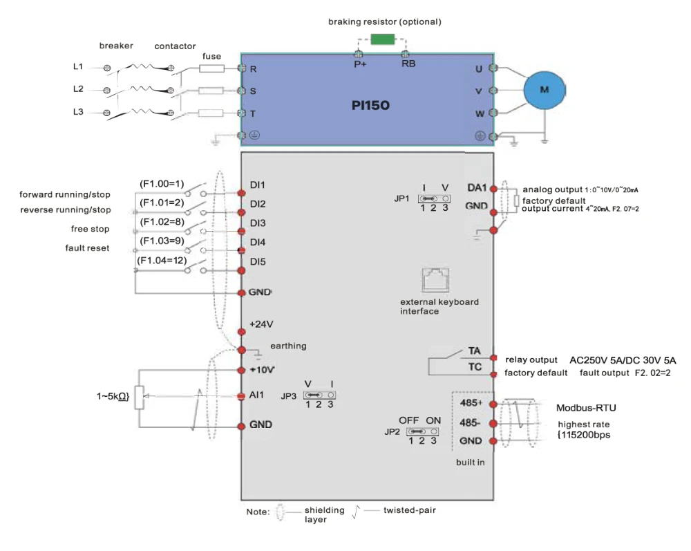
DI Input Terminal |
5 digital input terminals |
| Input Signal |
AI1 Analog Input |
1 analog input terminals respectively for optional range (0 to 20mA or 0 to 10V) |
| Input Signal |
Multi-Speed |
At most 16-speed can be set (run by using the multi-function terminals or program) |
| Input Signal |
Emergency Stop |
Interrupt controller output |
| Input Signal |
Fault Reset |
When the protection function is active, you can automatically or manually reset the fault condition |
| Input Signal |
PID Feedback Signal |
Including DC (0 to 10V), DC (0 to 20mA) |
| Output Signal |
Output Signal |
One way relay output; One way AD1 analog output |
| Output Signal |
Relay Output |
There are 40 signals each way.
Contact capacity: normally open contact 5A/AC 250V, 1A/DC 30V |
| Output Signal |
DA1 Analog Output |
One way analog output, can select frequency, current, voltage etc 16 signals. Output signals can be sent 0~10V/0~20mA |
| Running Command Channel |
Three channels: operation panel, control terminals and serial communication port. They can be switched through a variety of ways |
| Frequency Source |
Total 7 frequency sources: digital, analog voltage, analog current, multi-speed and serial port. They can be switched through a variety of ways |
| Run Function |
Limit frequency, jump frequency, frequency compensation, auto-tuning, PID control |
| Protection Function |
| Inverter Protection |
Overvoltage protection, undervoltage protection, overcurrent protection, overload protection, overheat protection, overcurrent stall protection, overvoltage stall protection, lost-phase protection (optional), communication error, PID feedback signal abnormalities, PG failure and short circuit to ground protection |
| Display |
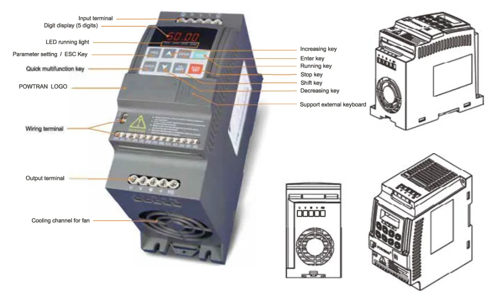
| LED Display Keyboard |
Running Information |
Monitoring objects including: running frequency, set frequency, bus voltage, output voltage, output current, output power, output torque, input terminal status, output terminal status, analog AI1 value, motor Actual running speed, PID set value percentage, PID feedback value percentage |
| LED Display Keyboard |
Error Message |
Up to three error messages are saved. The time, type, voltage, current, frequency and work status can be queried when a failure has occurred |
| Key Lock and Function Selection |
The keypad can be partially or fully locked, define the function scope of some keys to prevent misuse |
| IGBT Temperature |
Show the inverter inner IGBT temperature |
| Communication |
| RS485 |
Built in 485 |
| Environment |
| Environment Temperature |
-10℃ to 40℃ (temperature at 40℃to 50℃, please derating for use) |
| Storage Temperature |
-20℃ to 65℃ |
| Environment Humidity |
Less than 90% R.H, no condensation |
| Vibration |
Below 5.9m/s²(= 0.6g) |
| Application Sites |
Indoor where no sunlight, corrosive substance, explosive gas, water vapour, dust, flammable gas, oil, mist, salt, etc |
| Altitude |
No need to degrade use under 1000m, degrade 1% for altitude rise 100m when above 1000m, do not use it above 3000m |
| Protection Level |
IP20 |
| Product Standard |
| Product Adopts Safety Standards |
IEC61800-5-1:2007 |
| Product Adopts EMC Standards |
IEC61800-3:2005 |
| Cooling Method |
Forced air cooling |
| Install Method |
DIN-Rail mounting, wall mounting |