PXe-PA900 Three phase Power Analyser

The PXe-PA900 Three Phase Power Analyser is a high-performance and affordable power measurement device designed to meet the demands of various energy measurement applications. It offers both single and three-phase power analysis with exceptional accuracy and wideband measurement capabilities.

One of the standout features of the PXe-PA900 is its intuitive colour touchscreen user interface, which makes it easy to operate and navigate. Its accuracy surpasses many competing instruments that are priced significantly higher, making it a cost-effective choice for power analysis.

The PXe-900 excels in terms of speed and bandwidth, offering up to 100 readings (sets) per second and supporting measurement bandwidths capable of handling 5 MHz waveforms. This makes it suitable for tackling demanding power factor, low phase angle, and high crest factor loads. With a crest factor performance of up to 25:1, the PXe-900 provides modern power measurement capabilities.

The power analyser is particularly useful for challenging power measurement applications where energy conservation and minimising losses are crucial. Design engineers working on power electronics devices, such as LED and HID lighting, solar panel energy output, efficiency testing on inverters, and PWM motor drive systems in electric vehicles, require fast, precise, and reliable power measurement. The PXe-PA900, with its three-phase, three-channel (and optional four-channel) configuration, offers a solution that provides accurate waveform capture and power data analysis. This allows engineers to optimise energy efficiency and minimise power consumption in their projects.

In addition to its hardware capabilities, the PXe-PA900 is supported by dedicated software and drivers, enhancing its productivity and enabling users to extract valuable insights from captured waveforms and power data.

In summary:

Overall, the PXe-PA900 Three Phase Power Analyser is a comprehensive and cost-effective solution for demanding power measurement applications, providing accurate results and supporting engineers in their quest for energy efficiency and reduced power losses.

View our other models in the PXe-PA9xx Series:

PXe-920 Three Phase, Multi Channel Power Analyser

PXe-910 High Accuracy (0.045%) Precision Multi-Channel Power Analyzer

PXe-PA9xx Flexible multi channel Power Analyser

Description

High Accuracy & Wide Bandwidth
Easy-to-Use Touchscreen Operation
All the Data you need at a Price you can Afford

Introducing the PXe-PA900 Precision Harmonic Power Analyzer, an easy-to-use high performance power analyzer at a reasonable price. The PA900 delivers multi-channel, high-accuracy, wideband performance – to tackle the toughest energy measurement applications.  PXe has the experience to deliver world class power measurement capability at a price that is affordable.

The PXe-900 Power and Harmonic Power Analyzer at work:

PXe-900 tech

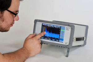
The new PXe-900 boasts an impressive array of precision power measurement capabilities like W, VA, VAR, PF, Cosphi and Fundamentals, yet its colour touchscreen user interface is easy to use. The accuracy options of the PA900 allows choice – surpassing rival instruments costing triple the price. And when it comes to speed & bandwidth – the PXe-900 offers features like 100 full precision readings per second and measurement bandwidths sufficient to handle 5 MHZ waveforms – associated with Power Electronics and EV. For tackling complex power factor, low phase angle and high crest factor loads – the PA900 is unbeatable. Offering full performance for crest factors as high as 30:1 – the PA900 places the advantage of superior power measurement capability in the palm of your hands or if you prefer – at the tip of your finger.

The Best Solution for the Toughest Power Measurement Applications

Energy is one of our most precious resources, design engineers are under constant pressure to increase efficiency and reduce excess product power consumption down to the last mW. Challenging applications like LED and HID lighting, solar panel energy output, efficiency testing on inverters and PWM motor drive systems on electric vehicles – all require fast, precise, reliable power measurement. The unequalled performance of the PXe-900 gives you the competitive advantage – the ability to accurately capture the waveforms and complex power data needed to know how to make energy savings on your project.

Harmonics Screen

Harmonics Screen

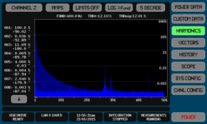
To meet advanced power harmonics requirements, the PA900 displays up to 500 harmonics even at aviation power frequencies. The chart can be set to show linear, relative linear, logarithmic or relative logarithmic amplitudes. Additionally, 8 harmonics can be selected for numeric display of amplitude and phase by touching the harmonic bar of interest. The user may also import harmonic limits (like EN61010), which when enabled will show out of tolerance harmonics in red above the limit line.
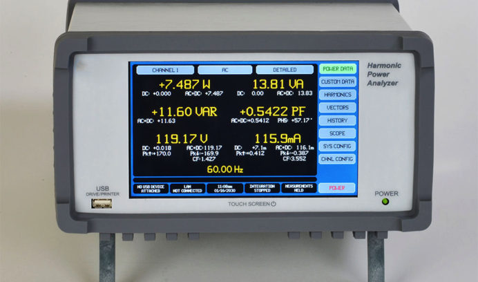
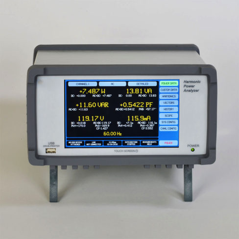
Power Data Screen

Screen

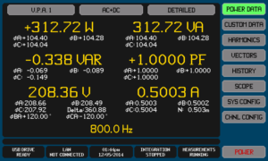
The power data screen, available with one touch, displays V, A, W, VA, VAR and PF data (and fundamentals) for any selected channel or group of channels known as a Virtual Power Analyzer™ (VPA). Up to three different VPAs can exist in in a single PA900. In addition to the primary data, peak readings, phase, CF and other parameters are also available. Integrated data results (WHr) can also be controlled and viewed from the power data screen. For users with unique data requirements, custom data screens can be built with a spreadsheet application and downloaded to the PXe-900 via interface or USB drive.

Scope View

Scope View Screen

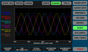
Scope view offers waveform acquisition and analysis similar to a digital scope. Up to 6 signals can be displayed, each having user selectable scaling, offset and colour. Timebase, trigger and trigger position are all user selectable. However, with amplitude accuracies as high as 0.03% – you are unlikely to find any other scope with this high level of precision.  A valuable diagnostic tool.

Cycle View

Cycle view

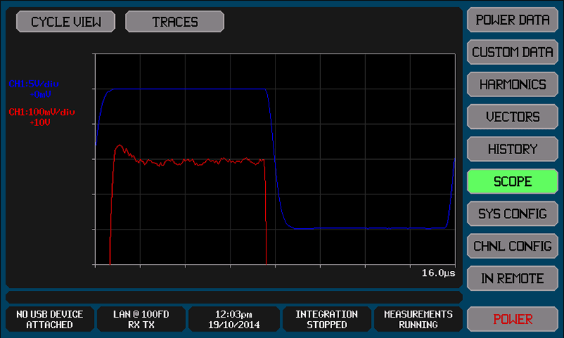
The cycle view represents a single cycle of the voltage and or current periodic waveforms. The above waveforms represent a full 10V square wave in blue and a 50:1 zoomed in view in red. Since the user sets amplitude and scaling – the result is an almost unlimited ability to amplitude zoom to expose fine detail. The sampling is forced to be asynchronous to higher order harmonics which leads to an effective sampling rate of 384MSPS.

Vector Screen

Vector Screen

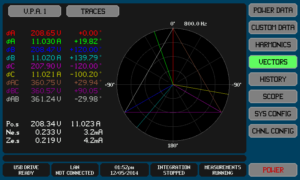
A vector-polar chart graphically displays the fundamental voltage and current vectors for the selected channel or VPA. For multi-phase VPAs, the inter-phase voltages and non-measured neutral phase vectors are displayed. The user may enable the display of and select the colour of each vector up to a maximum of 10.

History Screen

History Screen

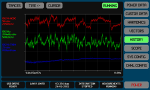
The PXe-900 automatically maintains a continuous historical record of all non-harmonic measurement results and selected harmonics. Up to four user selectable parameters can be graphically displayed using the HISTORY screen. The user can display the entire recorded period up to 397 days or zoom in as far as 1/64th of the total span. This provides an almost unlimited ability to amplitude zoom and includes a cursor which may be moved throughout the period with a touch of the screen.

Standby Power Screen

Standby Screen

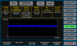
The PXe-900 features built in standby power testing in accordance to EN50564:2011 (replaces IEC62301) which can be started with the press of a finger from the STBY POWER screen. All information is neatly organised onto a single screen for easy viewing and can just as easily be saved as an image file into a connected USB drive to add into any report. Various measurement methods laid out in EN50564:2011, minimum test time, and data logging capability are all selectable. The PXe-900 also has the ability to perform standby power measurements independently in each configured VPA.

Modular Design means Flexibility

The PXe-900 uses a modular design approach to provide the performance you need at a price that meets your budget. A single PXe-900 chassis holds up to 4 Channels of power measurement in any combination of three different Channel types.

  • The S type Channel card provides economical, high performance power measurement with a basic 0.1% accuracy and enough bandwidth to handle waveforms up to 1.25 MHz.
  • The A type ultra-precision Channel card offers a 2 year accuracy rating of 0.03% of reading and bandwidth up to 1.25 MHz.
  • The W type Wideband Channel card performs precision power measurements on the toughest real world waveforms, with sampling speed fast enough to tame waveforms up to 5MHz

And speaking of flexibility, each of the above Channel cards is available with your choice of 3 different current input options. The D current input option uses an auto-ranging Dual Shunt system to deliver precision current measurement from as low as 0.1micro-amp resolution on the 1 amp range up to 20Arms on the high range. For higher current measurements, the H current input option operates from 10 uA resolution up to 30Arms. The X input current option is designed to provide optimum compatibility with a wide range of external shunts and current transducers. PXe makes it easy for you to configure a harmonic power analyzer that is perfect for your application.

Product Features

  • Most advanced Power Measurement Platform with an unprecedented range of capabilities
  • Highest Precision with Industry leading noise floor – as low as 1ppm vs 300ppm or more on competitive units
  • Up to 500 Harmonics at 400Hz, meets Airbus avionics harmonics measurement criteria. Bar graph also features fingertip selectable numeric amplitude and phase data
  • Large, Hi-Resolution Color Display shows all the data you want with an easy-to-use touchscreen user interface to get you up and testing in no time
  • Modular design lets you choose up to 4 Power Measurement Channel Cards in any combination of 3 different Channel Card types
  • The S type Channel Card provides 0.1% basic Accuracy with 1 MHz class bandwidth for an extremely economical price
  • The A type Channel Card offers world class 0.03% basic accuracy with 1MHz class bandwidth at a very reasonable cost
  • The L type Channel Card offers capabilities similar to the A card but optimized for levels below 100V with resolution down to 10uV
  • The W type Channel Card delivers 5 MHZ class bandwidth and a 0.1% basic accuracy
  • All Channel Cards types are available with one of 3 current input options: D – Dual Shunt, H – High Current and X – External Current Transducer Input
  • Built-in Data Logger – Logs up to 16 selectable data results to USB thumbdrive or internal data storage. Intervals from 10mS to 100 hours with optional time/date stamps
  • Power Data Screen – displays V, A, W, VA, VAR and PF data for any selected channel or group of channels
  • Custom Power Data Screens – lets you choose the color, font size, location and data you want displayed
  • With selectable time base and triggering – Scope View, acts as a digital scope to capture events such as in-rush current
  • Cycle View – Represents a single cycle of the voltage and current periodic waveforms sampled over many cycles within a measurement period
  • Vector Screen – Displays up to 10 fundamental voltage & current vectors
  • History Screen – Like a DVR, the PA900 automatically maintains a continuous historical recording of measurement data. Any data from this record may be viewed or downloaded. Pause, clear & restart functionality is available from the HISTORY screen or via interface
  • Standby Power Screen – Test in accordance to EN50564:2011 with an easy to set up, easier to use built in application. One screen holds all of your necessary data.
  • Effective Sampling Rate – for analysis of periodic signals within a measurement period is 384MSPS
  • Measurement Resolution – 22 bit for S & W type Channel Cards, 24 bit for A type
  • Up to 3 Different Virtual Power Analyzers™ (VPAs) may be configured for three phase measurements or input/output efficiency tests – so there is no need to interconnect separate units in order to make synchronous or non-synchronous group power measurements
  • VPA Efficiency Grouping – Available data includes: Power totals for IN, MIDDLE and OUT efficiency groups, the power loss between any pair of groups, and the percentage efficiency between any pair of groups
  • VPA Multi-Channel Wiring – Each VPA may be configured as 2ø3w (2 ch), 3ø3w (2 ch), 3ø3w (3 ch), 3ø4w (3 ch)
  • Connectivity – Ethernet, High Speed Serial and USB (client) control interfaces
  • Optional Multi-Unit (Option MU) connection available to combine multiple PA900 units to enable you to make measurements with up to thousands of channels
  • Front Panel USB Drive Interface – Permits data logging to a file, ‘screen shot’ capture, easy import and export of: display and measurement configurations & custom data screen definitions
  • Available MT type Channel Card for motor torque & speed inputs
  • CE mark certified to EN61010
  • 2 Year Parts & Labour Warranty, 2 Year Accuracy Specs and calibration cycle

PA900 Performance Specifications

Voltage Input Specifications

S or A Channel W Channel
Specified Input Range DC 0 to ±1000V 0 to ±700V
AC 0.1 to 1000Vrms 0.1 to 700Vrms
Peak <1800V <1800V
Safe Input Range <1ms 2500Vrms (<3000Vpk) 2000Vrms (<3000Vpk)
<100ms 2000Vrms (<3000Vpk) 1500Vrms (<3000Vpk)
<5s 1500Vrms (<2500Vpk) 1000Vrms (<2500Vpk)
Cont 1000Vrms (<1800Vpk) 700Vrms (<1800Vpk)
Impedance 1.2MΩ ± 1% 400KΩ ± 1%

Voltage Accuracy Specifications

The voltage input has a single dynamic range which covers the entire specified input range.
S Channel A Channel W Channel
Resolution 0.001V 0.1mV 0.001V
Base Accuracy 0.1%rdg 0.03%rdg 0.1%rdg
Frequency Adder 0.01-1Hz: 0.05%rdg
<10KHz: (0.005*F)%rdg
10-40KHz: (0.05+(0.012*(F‐10)))%rdg
40-100KHz: (0.41+(0.025*(F‐40)))%rdg
0.01-1Hz: 0.01%rdg
<40KHz: (0.002*F)%rdg
40-100KHz: (0.08+(0.04*(F‐40)))%rdg
100-1000KHz: (0.32+(0.013*(F‐100)))%rdg
Bandwidth (-3dB) >700KHz >2.5MHz
Floor Adder DC: 0.002V
AC<100Hz: 0.003V
AC>100Hz: 0.005V
DC: 0.001V
AC<100Hz: 0.002V
AC>100Hz: 0.005V
DC: 0.003V
AC<100Hz: 0.004V
AC>100Hz: 0.007V
Self-Heating Adder >0.0005ppm rdg per Vrms2 0.0015ppm rdg per Vrms2
Single Harmonic Adder <10KHz: 0.01%fund + 0.001V
<85KHz: 0.05%fund + 0.005V
<10KHz: 0.005%fund + 0.0005V
<85KHz: 0.05%fund + 0.005V
<10KHz: 0.015%fund + 0.0015V
<100KHz: 0.03%fund + 0.005V
<310KHz: 0.08%fund + 0.01V
ΣHarmonic Adder <10KHz: 0.02%fund + 0.002V
<85KHz: 0.1%fund + 0.01V
<10KHz: 0.015%fund + 0.001V
<85KHz: 0.15%fund + 0.01V
<10KHz: 0.03%fund + 0.003V
<100KHz: 0.06%fund + 0.007V
<310KHz: 0.15%fund + 0.015V
CMRR >1uV per V.Hz 0.7uV per V.Hz
Inter-Channel Phase (0.02° + 0.15°*F) (0.02° + 0.07°*F)

Current Input Specifications

H option D option X option
AUTO range HI range LO range HI range LO range
Specified Input Range DC 0 to ±30A 0 to ±20A 0 to ±20A 0 to ±1A 0 to ±15V 0 to ±0.5V
<100Hz 3mA to 30Arms 10uA to 20Arms 2mA to 20Arms 10uA to 1Arms 800uV to 15Vrms 20uV to 0.5Vrms
>100Hz 20mA to 30Arms 150uA to 20Arms 15mA to 20Arms 150uA to 1Arms 2mV to 15Vrms 80uV to 0.5Vrms
Peak <200A <50A <150A <1A <18V <0.5V
Safe Input Range <1ms 200Arms
(<300Apk)
30Arms
(<50Apk)
150Arms
(<250Apk)
30Arms
(<50Apk)
200Arms
(<300Apk)
20Arms
(<300Apk)
<20ms 75Arms (<300Apk) 20Arms (<50Apk) 50Arms (<200Apk) 20Arms (<50Apk) 50Vrms (300Vpk) 10Vrms (200Vpk)
<1s 50Arms (<200Apk) 20Arms (<50Apk) 30Arms (<150Apk) 5Arms (<25Apk) 30Vrms (300Vpk) 5Vrms (100Vpk)
Cont 30Arms 20Arms (<50Apk) 20Arms (<150Apk) 2Arms (<5Apk) 20Vrms (300Vpk) 2Vrms (50Vpk)
Power Off As Above As LO Range As Above As HI Range
Impedance <10mΩ As HI/LO range <20mΩ 0.57Ω ± 10% 20.5KΩ ± 1% 10.25KΩ ± 1%

H Option Current Measurement Accuracy Specifications

The H option current input has a single range which covers the entire specified input range.
S Channel A Channel W Channel
Resolution 100uA 10uA 100uA
Base Accuracy 0.1%rdg 0.03%rdg 0.1%rdg
Frequency Adder 0.01‐1Hz: 0.05%rdg
<10KHz: (0.003*F)%rdg
10‐40KHz: (0.03+(0.007*(F‐10)))%rdg
40-100KHz: (0.24+(0.02*(F‐40)))%rdg
0.01‐1Hz: 0.1%rdg
<40KHz: (0.0015*F)%rdg
40‐100KHz: (0.06+(0.003*(F-40)))%rdg
100‐1000KHz: (0.24+(0.012*(F‐100)))%rdg
Bandwidth (‐3dB) >1.25MHz >5MHz
Floor Adder DC: 200uA
AC<100Hz: 800uA
AC>100Hz: 3mA
DC: 100uA
AC<100Hz: 500uA
AC>100Hz: 2mA
DC: 300uA
AC<100Hz: 1mA
AC>100Hz: 4mA
Self-Heating Adder 1.5ppm reading per Arms2
Single Harmonic Adder <10KHz: 0.01%fund + 100uA
<85KHz: 0.05%fund + 5mA
<10KHz: 0.005%fund + 80uA
<85KHz: 0.03%fund + 5mA
<10KHz: 0.015%fund + 150uA
<100KHz: 0.03%fund + 5mA
<310KHz: 0.08%fund + 5mA
ΣHarmonic Adder <10KHz: 0.02%fund + 200uA
<85KHz: 0.1%fund + 7mA
<10KHz: 0.015%fund + 150uA
<85KHz: 0.15%fund + 7mA
<10KHz: 0.03%fund + 300uA
<100KHz: 0.06%fund + 7mA
<310KHz: 0.15%fund + 10mA
CMRR 500pA per V.Hz
V:A Phase (0.01° + 0.015°*F) (0.01° + 0.007°*F)
Inter-Channel Phase (0.02° + 0.15°*F) (0.02° + 0.07°*F)

D Option HI Range Current Measurement Accuracy Specifications

The D option current input has two ranges, this section covers the HI range which covers the entire specified HI input range.
S Channel A Channel W Channel
Resolution 100uA 10uA 100uA
Base Accuracy 0.1%rdg 0.03%rdg 0.1%rdg
Frequency Adder 0.01‐1Hz: 0.05%rdg
<10KHz: (0.003*F)%rdg
10‐40KHz: (0.03+(0.007*(F-10)))%rdg
40-100KHz: (0.24+(0.02*(F‐40)))%rdg
0.01‐1Hz: 0.1%rdg
<40KHz: (0.0015*F)%rdg
40‐100KHz: (0.06+(0.003*(F‐40)))%rdg
100‐1000KHz: (0.24+(0.012*(F‐100)))%rdg
Bandwidth (‐3dB) >1.25MHz >5MHz
Floor Adder DC: 200uA
AC<100Hz: 500uA
AC>100Hz: 2mA
DC: 100uA
AC<100Hz: 300uA
AC>100Hz: 1.5mA
DC: 300uA
AC<100Hz: 700uA
AC>100Hz: 3mA
Self-Heating Adder 2ppm reading per Arms2
Single Harmonic Adder <10KHz: 0.01%fund + 70uA
<85KHz: 0.05%fund + 3.5mA
<10KHz: 0.005%fund + 50uA
<85KHz: 0.03%fund + 3.5mA
<10KHz: 0.015%fund + 100uA
<100KHz: 0.03%fund + 3.5mA
<310KHz: 0.08%fund + 4mA
ΣHarmonic Adder <10KHz: 0.02%fund + 150uA
<85KHz: 0.1%fund + 5mA
<10KHz: 0.015%fund + 120uA
<85KHz: 0.15%fund + 5mA
<10KHz: 0.03%fund + 200uA
<100KHz: 0.06%fund + 5mA
<310KHz: 0.15%fund + 7mA
CMRR 400pA per V.Hz
V:A Phase (0.01° + 0.015°*F) (0.01° + 0.007°*F)
Inter-Channel Phase (0.02° + 0.15°*F) (0.02° + 0.07°*F)

D Option LO Range Current Measurement Accuracy Specifications

The D option current input has two ranges, this section covers the LO range which covers the entire specified LO input range.
S Channel A Channel W Channel
Resolution 1uA 0.1uA 1uA
Base Accuracy 0.1%rdg 0.03%rdg 0.1%rdg
Frequency Adder 0.01‐1Hz: 0.05%rdg
<10KHz: (0.003*F)%rdg
10‐40KHz: (0.03+(0.007*(F-10)))%rdg
40-100KHz: (0.24+(0.02*(F‐40)))%rdg
0.01‐1Hz: 0.1%rdg
<40KHz: (0.0015*F)%rdg
40‐100KHz: (0.06+(0.003*(F‐40)))%rdg
100‐1000KHz: (0.24+(0.012*(F-100)))%rdg
Bandwidth (‐3dB) >1.25MHz >6MHz
Floor Adder DC: 2uA
AC<100Hz: 3uA
AC>100Hz: 10uA
DC: 1uA
AC<100Hz: 1.5uA
AC>100Hz: 8uA
DC: 3uA
AC<100Hz: 4uA
AC>100Hz: 15uA
Single Harmonic Adder <10KHz: 0.01%fund + 0.4uA
<85KHz: 0.05%fund + 20uA
<10KHz: 0.005%fund + 0.3uA
<85KHz: 0.03%fund + 20uA
<10KHz: 0.015%fund + 0.5uA
<100KHz: 0.03%fund + 20uA
<310KHz: 0.08%fund + 30uA
ΣHarmonic Adder <10KHz: 0.02%fund + 1uA
<85KHz: 0.1%fund + 30uA
<10KHz: 0.015%fund + 0.7uA
<85KHz: 0.15%fund + 30uA
<10KHz: 0.03%fund + 1uA
<100KHz: 0.06%fund + 30uA
<310KHz: 0.15%fund + 40uA
CMRR 20pA per V.Hz
V:A Phase (0.01° + 0.015°*F) (0.01° + 0.007°*F)
Inter-Channel Phase (0.02° + 0.15°*F) (0.02° + 0.07°*F)

X Option HI Range Current Measurement Accuracy Specifications

The X option current input has two ranges, this section covers the HI range which covers the entire specified HI input range.
S Channel A Channel W Channel
Resolution 1uV 0.1uV 1uV
Base Accuracy 0.1%rdg 0.03%rdg 0.1%rdg
Frequency Adder 0.01-1Hz: 0.05%rdg
<10KHz: (0.003*F)%rdg
10‐40KHz: (0.03+(0.007*(F‐10)))%rdg
40-100KHz: (0.24+(0.02*(F‐40)))%rdg
0.01‐1Hz: 0.1%rdg
<40KHz: (0.0015*F)%rdg
40‐100KHz: (0.068+(0.004*(F-40)))%rdg
100‐1000KHz: (0.308+(0.015*(F‐100)))%rdg
Bandwidth (‐3dB) >1.25MHz >3MHz
Floor Adder DC: 2uV
AC<100Hz: 2uV
AC>100Hz: 8uV
DC: 1uV
AC<100Hz: 1.5uV
AC>100Hz: 5uV
DC: 2uV
AC<100Hz: 3uV
AC>100Hz: 10uV
Single Harmonic Adder <10KHz: 0.01%fund + 0.3uV
<85KHz: 0.05%fund + 10uV
<10KHz: 0.005%fund + 0.1uV
<85KHz: 0.03%fund + 10uV
<10KHz: 0.015%fund + 0.3uV
<100KHz: 0.03%fund + 10uV
<310KHz: 0.08%fund + 15uV
ΣHarmonic Adder <10KHz: 0.02%fund + 0.5uV
<85KHz: 0.1%fund + 15uV
<10KHz: 0.015%fund + 0.3uV
<85KHz: 0.15%fund + 15uV
<10KHz: 0.03%fund + 0.5uV
<100KHz: 0.06%fund + 15uV
<310KHz: 0.15%fund + 20uV
CMRR 1nV per V.Hz
V:A Phase (0.01° + 0.015°*F) (0.01° + 0.007°*F)
Inter-Channel Phase (0.02° + 0.15°*F) (0.02° + 0.07°*F)

X Option LO Range Current Measurement Accuracy Specifications

The X option current input has two ranges, this section covers the LO range which covers the entire specified LO input range.
S Channel A Channel W Channel
Resolution 1uV 0.1uV 1uV
Base Accuracy 0.1%rdg 0.03%rdg 0.1%rdg
Frequency Adder 0.01‐1Hz: 0.05%rdg
<10KHz: (0.003*F)%rdg
10‐40KHz: (0.03+(0.007*(F‐10)))%rdg
40-100KHz: (0.24+(0.02*(F‐40)))%rdg
0.01‐1Hz: 0.1%rdg
<40KHz: (0.0015*F)%rdg
40‐100KHz: (0.068+(0.004*(F‐40)))%rdg
100‐1000KHz: (0.308+(0.015*(F‐100)))%rdg
Bandwidth (‐3dB) >1.25MHz >3MHz
Floor Adder DC: 2uV
AC<100Hz: 2uV
AC>100Hz: 8uV
DC: 1uV
AC<100Hz: 1.5uV
AC>100Hz: 5uV
DC: 2uV
AC<100Hz: 3uV
AC>100Hz: 10uV
Single Harmonic Adder <10KHz: 0.01%fund + 0.3uV
<85KHz: 0.05%fund + 10uV
<10KHz: 0.005%fund + 0.1uV
<85KHz: 0.03%fund + 10uV
<10KHz: 0.015%fund + 0.3uV
<100KHz: 0.03%fund + 10uV
<310KHz: 0.08%fund + 15uV
ΣHarmonic Adder <10KHz: 0.02%fund + 0.5uV
<85KHz: 0.1%fund + 15uV
<10KHz: 0.015%fund + 0.3uV
<85KHz: 0.15%fund + 15uV
<10KHz: 0.03%fund + 0.5uV
<100KHz: 0.06%fund + 15uV
<310KHz: 0.15%fund + 20uV
CMRR 1nV per V.Hz
V:A Phase (0.01° + 0.015°*F) (0.01° + 0.007°*F)
Inter-Channel Phase (0.02° + 0.15°*F) (0.02° + 0.07°*F)

Watts, VAR and VA Measurement Accuracy Specifications

Fundamental Phase Adder (for W or VAR only, typically can be ignored for active loading where the PF is reduced by distortion rather than phase shift. K is 0.3 for Watts, harmonic VAR and harmonic VA otherwise 1.0.
S Channel A Channel W Channel
Base Accuracy 0.17%rdg 0.05%rdg 0.17%
Frequency Adder Add Frequency Adders for voltage and current
Floor Adder DC: Vdc*(DC Current Floor Adder) + Adc*(DC Voltage Floor Adder) + (DC Voltage Floor Adder)*(DC Current Floor Adder)
AC: Vac*K*(AC Current Floor Adder) + Aac*K*(AC Voltage Floor Adder)
Fundamental Phase Adder Watts: VAfund*(PFfund – cos(cos-1(PFfund) + V:A phase for current input))
VAR: VAfund*((1‐PFfund) ‐ cos(cos‐1(1‐PFfund) + V:A phase for current input))
Self‐Heating Adder Add Self‐Heating Adders for voltage and current
Single Harmonic Adder Add Single Harmonic Adders for voltage and current
ΣHarmonic Adder Add ΣHarmonic Adders for voltage and current
Star Icon

Quality

We are committed to providing products that meet international quality requirements. PX Electronic certifies that all products meet or exceed their published specification, European & USA safety requirements.

Find Out More
box icon

Shipping

At PX Electronics all of our products are available to ship worldwide.

Use the link below to view our product range.

View Now
question mark icon

FAQ’s

If you can’t find the answer you’re looking for?

Dont worry we have shared some of our most frequently asked questions to help you.

Read more